Once again, Do you remember how to read sensors
-digital sensor (PushButton)
-analog sensor (photoCell)
Challenge:
Connect push button or photocell to your Arduino and control a LED connected to Arduino
RGB LED
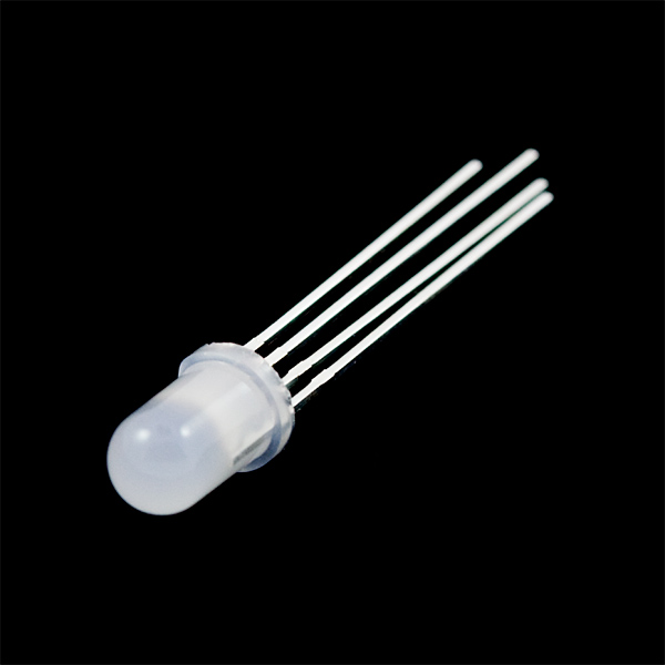
RGB LED is something like 3 LED (red, green, blue) in one with common cathode or anode (The one we have is common cathode). You can control voltage applied to each pins to control the intensity of red, green or blue.. meaning you can display any color you like with this LED by mixing RGB.
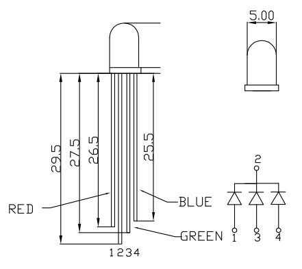
Features:
Forward Voltage (RGB): (2.0, 3.2, 3.2)V
Max Forward Current (RGB): (20, 20, 20)mA
Max Luminosity (RGB): (2800, 6500, 1200)mcd
Resister for LED?
Until now, we were using LEDs directly connected to digital pins and applying 5V, but this is actually not recommended. You should apply the current recommended on the datasheet on each LED. Commonly, many non-bright LEDs (like the ones we used in the second week) are 20mA, 2.3 forward voltage.
By adding the correct value resister on your circuit, you can limit the current flowing through the LED. This will protect the LED from breaking. If you do not use resister and apply 5V for longer time, it may eventually break.
Here is how you calculate the value for the current limiting resister, using ohm’s law.
(Supply voltage – forward drop voltage) / forward current
Supply Voltage: the voltage you supply the LED circuit with. For example if you are using Arduino Uno, your digital pin gives out 5V, so the supply voltage is 5V.
Forward Drop Voltage: How much Voltage the LED need. This is specified on the LED’s datasheet. Typically 2.3-3V
Forward Current: How much current the LED need. if it is written in mA, divide it by 1000 to convert to A. Typically 20-30mA.
We will be connecting the each pins to digital output pins, which supply 5V. Which of the resisters should we add to each pins?
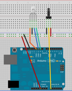
Let’s connect RGB LED to Digital Pin 9,10,11 and control the color change with potentiometer.
Challenge:
Can you use potentiometer to cycle through the rainbow color change?
Transistor Switch
When you are controlling actuator that needs more than 5V or more than 40mA (this is the maximum current digital pins can supply), you can not directly drive this actuator from the digital pins.
So, idea is that if you could control a switch like this with Arduino
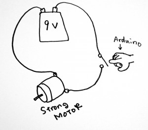
You can do this by using a Transistor as Switch.
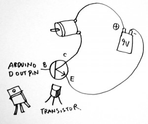
or if I write it in schematic way, it is like this
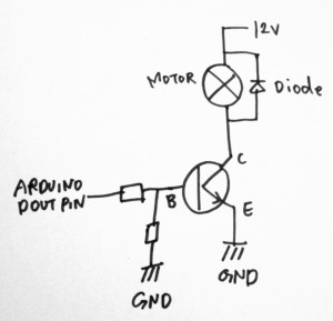
The transistor used here is NPN type one, which by default (0V on base pin) is OFF and it turns ON when you apply voltage on base pin.
Transistor pins
B: Base. You can control ON/OFF state of the transistor switch by applying voltage (i.e. 5V)
C: Collector. On NPN type transistor switch circuit, load (i.e. motor) is above the collector pin
E: Emitter. On NPN type transistor switch circuit, Emitter connects to GND. When voltage is applied to Base pin, Collector and Emitter gets closed (connected).
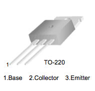
We use TIP122 for the course today
TIP122 datasheet
DC motor:
“When a current passes through the coil wound around a soft iron core, the side of the positive pole is acted upon by an upwards force, while the other side is acted upon by a downward force. According to Fleming’s left hand rule, the forces cause a turning effect on the coil, making it rotate. To make the motor rotate in a constant direction, “direct current” commutators make the current reverse in direction every half a cycle (in a two-pole motor) thus causing the motor to continue to rotate in the same direction.”
from Wikipedia
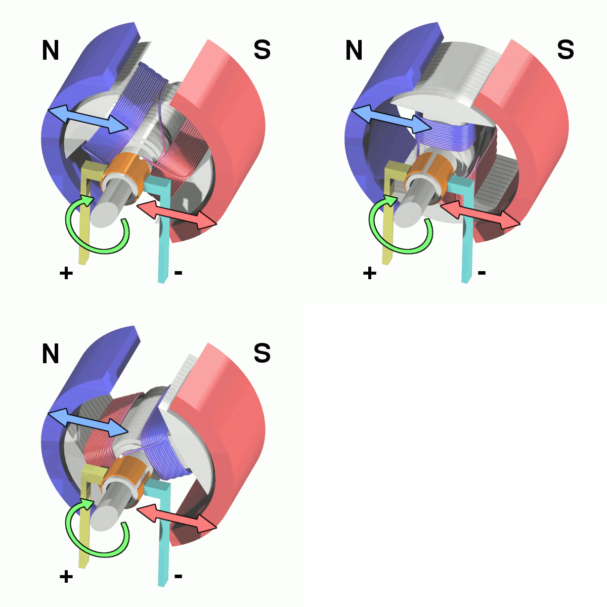
So, there are not really a direction (+, -) for the motor connection. If you reverse the direction, the motor turns in other direction.
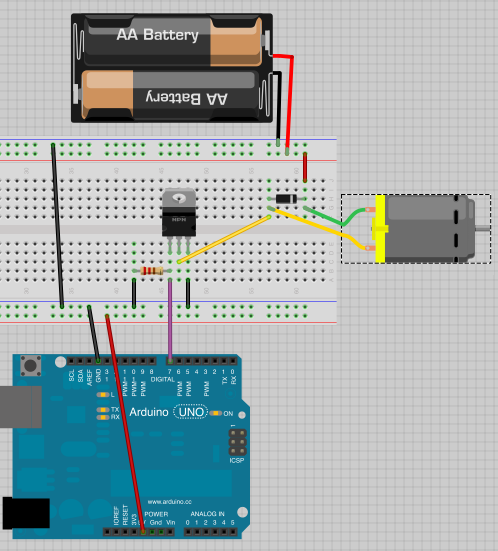
For now, we use 5V from Arduino for the motor power supply, and we skip the resistor between Arduino output pin and transistor’s base pin. The size of the resistor between Transistor’s base pin and GND is 100k ohm.
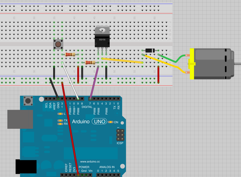
Challenge:
Can you make the project as such that when you push the button, the motor turns?
Challenge:
Now, change the push button to potentiometer. Can you control the speed of the motor with potentiometer? (hint: PWM and analogWrite)
Challenge:
Play with various digital/analog sensors to control the motor
H Bridge
Now, won’t it be nice if we could control the turning direction of the motor?
It is possible to control the turning direction using a component called H-Bridge.
“An H bridge is an electronic circuit that enables a voltage to be applied across a load in either direction. These circuits are often used in robotics and other applications to allow DC motors to run forwards and backwards.”
from wikipedia

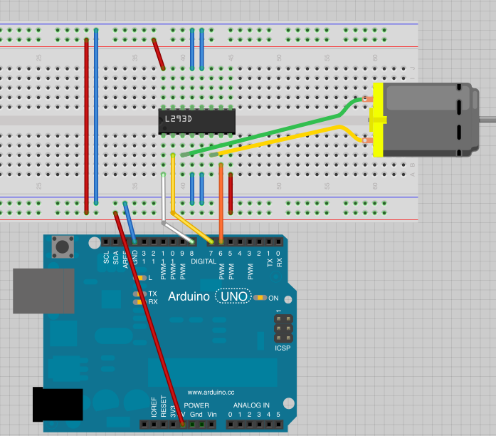
Here is a nice tutorial on how to use H bridge with motor and control it from Arduino >> http://itp.nyu.edu/physcomp/Labs/DCMotorControl
The pin connection schematic from the above tutorial

Connection breadboard view:
