DAY 2:
Do you remember what we did yesterday?
first exercise: Read push Button into digital input and control LED accordingly. LED turns on only when you press the button.
Do you remember how to connect push button to Arduino?
Data Type
We did not talk about this yesterday, but when you declare new variables, you declare data type, like “int”
There are different kinds of data type such as
boolean (0,1)
int (-32,768 to 32,767)
unsigned int (0 to 65,535)
long (-2,147,483,648 to 2,147,483,647)
float (as large as 3.4028235E+38 and as low as -3.4028235E+38)
char ( ‘A’, ‘B’, ‘C’)
So, as the buttonState is actually only be HIGH or LOW (1 or 0), the data type of the buttonState can be boolean instead of int.
Analog Read
Potentiometer
“A potentiometer, informally a pot, is a three-terminal resistor with a sliding contact that forms an adjustable voltage divider. If only two terminals are used, one end and the wiper, it acts as a variable resistor or rheostat.”
from wikipedia
inside of a potentiometer
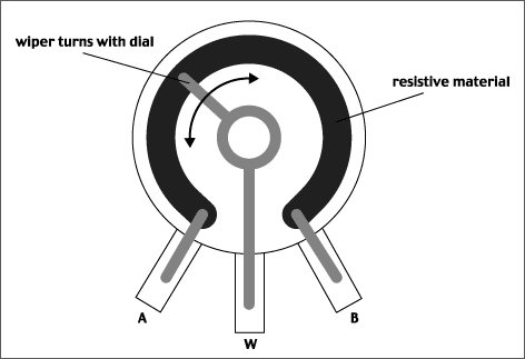
Let’s connect the potentiometer to multimeter, and read out the resistance change as you turn the knob. Connect multimeter’s proves to the first pin and the middle pin of the potentiometer.
How to connect with Arduino
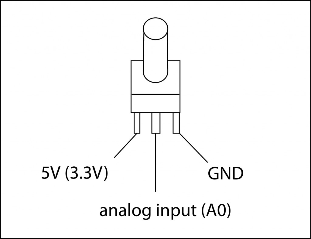
We work on this example: Analog Read Serial
Open it from File/Examples/Basic/AnalogReadSerial
What we cover:
Serial.begin()
AnalogRead()
Serial.println()
Serial Monitor

Analog Input Pins:
it will map input voltages between 0 and 5 volts into integer values between 0 and 1023
Voltage Divider:
You can divide the voltage by using 2 resisters.
If you have 2 exactly same resistors, the voltage gets half in the middle, like the first diagram.
As the ratio between two resisters changes, the voltage you get in the middle (between the resisters) changes accordingly.
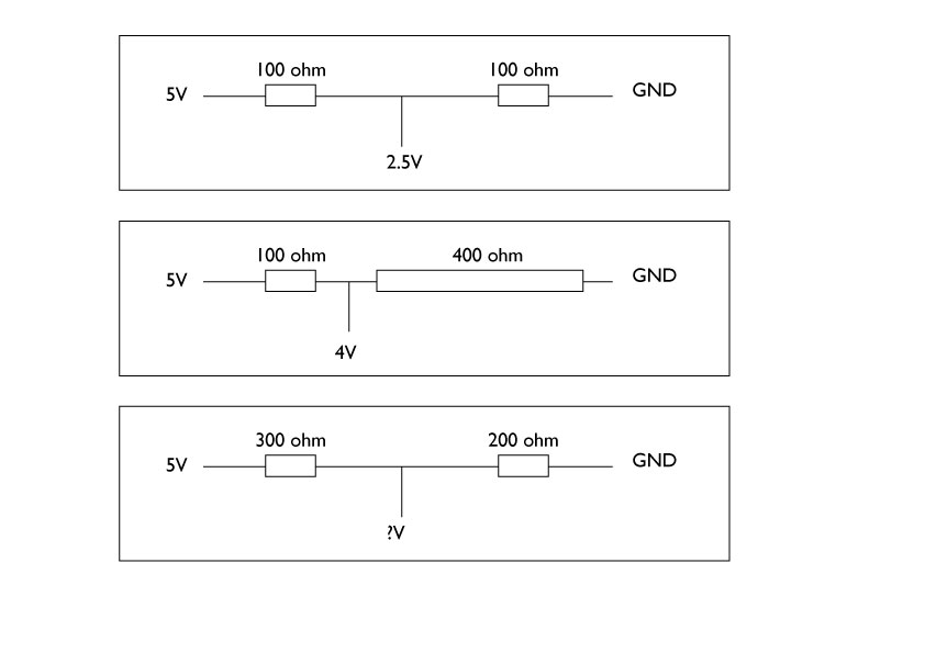
As the analog input pins are reading the voltage input changes, we need to change the voltage that goes into the analog pins by changing the resistance connected to the analog input pin. Potentiometer is acting as voltage divider, between left pin and middle pin as one resister, and the middle pin and right pin as another. As you turn the knob, the ratio of two resisters change, thus the voltage flowing into the middle pin changes.
Challenge:
Add LED on the potentiometer circuit.
When your potentiometer’s input is less than 500, turn the LED on.
Analog Write
We open AnalogInOutSeiral
Examples/Analog/AnalogInOutSerial
What does it do?
Reads an analog input pin, maps the result to a range from 0 to 255 and uses the result to set the pulsewidth modulation (PWM) of an output pin.
The microcontroller’s pins can only output 0V or 5V, and not 1.2V or 2.4V. So, to output voltage between 0V-5V smoothly, in another word to do “fading” affect, it mimics the 1.2V and 2.4V by pulsing 5V and 0V quickly and change the width of the pulsation. This called PWM.
You can read the explanation at Arduino site: Pulse Width Modulation (PWM)

Connection example:
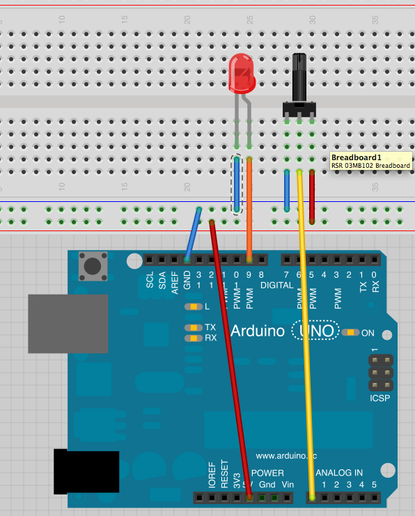
What we cover:
analogWrite()
map()
Challenge:
connect vibration motor instead of LED. Can you control it with potentiometer?
Photocell
“A photoresistor or light-dependent resistor (LDR) or photocell is a light-controlled variable resistor. The resistance of a photoresistor decreases with increasing incident light intensity; in other words, it exhibits photoconductivity.”
from wikipedia
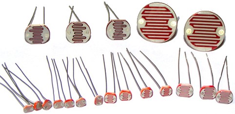
Measure the photocell’s resistance change with Multimeter.
What do you measure?
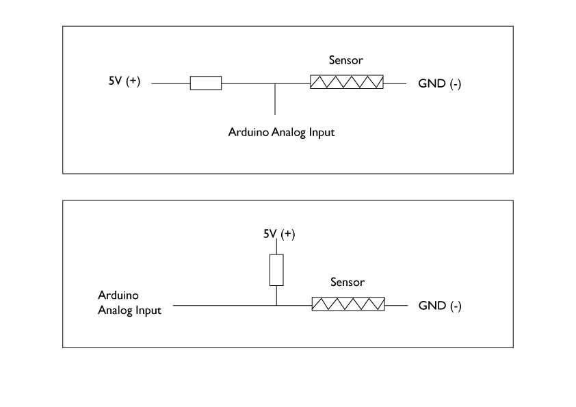
How to connect analog sensors
voltage divider

We did this in potentiometer part. Now we apply this to analog resistive sensors, like photocell.
How to connect analog sensors
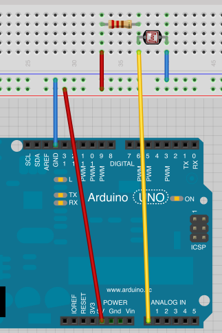
or if this was connected on the breadboard, it will be something like this
Challenge:
Connect Photocell to A0 pin.
What kind of input do you get? use Serial Monitor
Challenge:
Add LED on this circuit.
Program the Arduino so that when it is dark, it turns on the LED and when it is bright, turns off the LED
Challenge:
Now, can you use photocell to fade the LED?
You will need to use constrain() function.
You can download the Arduino Sketch and breadboard connection on Fritzing we used in the course from here
https://github.com/mikst/code/tree/master/101/week2
LED Fade Sequence
Instead of controlling the fading by a potentiometer, can we automatically fade LED in sequence?
Fade
Examples/Basic/Fade
Challenge:
Add push button to the circuit (remember how to connect it from yesterday?)
Use push button to start and stop the Fade Sequence.
Press button first time >> fading starts
Press button second time >> fading stops
You can download the Arduino Sketch and breadboard connection on Fritzing we used in the course from here
https://github.com/mikst/101