DAY 3:
Let’s see if we remember what we did yesterday.
Please make a project that has:
- a Photocell connected to A5
- a LED connected to D9
When you close the photocell with your finger, the Light slowly turns on.
LED Fade Sequence
Instead of controlling the fading by a potentiometer, can we automatically fade LED in sequence?
Fade
Examples/Basic/Fade
Challenge:
Add push button to the circuit (remember how to connect it from yesterday?)
Use push button to start and stop the Fade Sequence.
Press button first time >> fading starts
Press button second time >> fading stops
——
/*
Fade
This example shows how to fade an LED on pin 9
using the analogWrite() function.
This example code is in the public domain.
*/
int buttonPin=2;
int buttonState;
int pressCount;
int lastButtonState;
int led = 9; // the pin that the LED is attached to
int brightness = 0; // how bright the LED is
int fadeAmount = 5; // how many points to fade the LED by
// the setup routine runs once when you press reset:
void setup() {
// declare pin 9 to be an output:
pinMode(led, OUTPUT);
pinMode(buttonPin, INPUT);
Serial.begin(9600);
}
// the loop routine runs over and over again forever:
void loop() {
lastButtonState=buttonState;
buttonState=digitalRead(buttonPin);
if (lastButtonState==LOW){
if (buttonState==HIGH){
pressCount=pressCount+1;
}
}
/*
Serial.print(“pressCount : “);
Serial.print(pressCount);
Serial.print(” fadeAmount : “);
Serial.print(fadeAmount);
Serial.print(” brightness : “);
Serial.println(brightness);
*/
//fading up
if (pressCount==1){
fadeAmount=5;
if (brightness==255){
//if the light reaches full brightness, stay in full brightness
fadeAmount=0;
}
brightness=brightness+fadeAmount;
analogWrite(led,brightness);
}
//fading down
if (pressCount==2){
fadeAmount=-5;
brightness=brightness+fadeAmount;
analogWrite(led,brightness);
if (brightness==0){
pressCount=0;
}
}
if (pressCount>2){
pressCount=1;
}
// wait for 30 milliseconds to see the dimming effect
delay(30);
}
———-
servo motor
“A servomotor is a rotary actuator that allows for precise control of angular position, velocity and acceleration. It consists of a suitable motor coupled to a sensor for position feedback. It also requires a relatively sophisticated controller, often a dedicated module designed specifically for use with servomotors.”
(from wikipedia>

“As the name suggests, a servomotor is a servomechanism. More specifically, it is a closed-loop servomechanism that uses position feedback to control its motion and final position. The input to its control is some signal, either analogue or digital, representing the position commanded for the output shaft.”
(also from wikipedia)
RC (hobby) Servo motors often comes with 3 colored cables; Black (GND) RED (5V) and Yellow/orange (data). This types of servomotors includes the servomechanism controller inside, which you can send the angle controlling signal from the data line.
Arduino has implemented a library to control the servomotor, called servo library. You can read more about it here
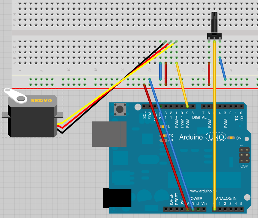
Open the Knob sketch from Examples/Servo/knob
This sketch will allow you to control potentiometer connected to A0 pin to control a servo motor connected to Pin9.
Here is how you connect:

What we cover:
including Library
servo.attach()
servo.write()
Challenge:
Can we use photocell to control the servo motor?
You can download the Arduino Sketch and breadboard connection on Fritzing we used in the course from here
https://github.com/mikst/101