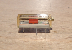
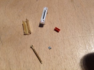
The device I took apart is a Potentiometer Knob..
So let’s see how it works!
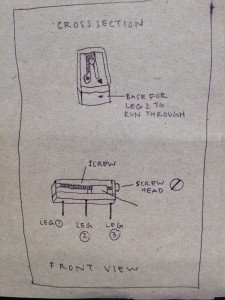
It is made of a base with three legs, a slider, a screw and a top cover.
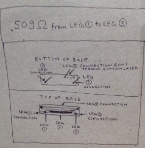
Legs 1 & 3 are connected through a high resistance pathway on top of the base. Leg 2 is connected to a very low resistance pathway on top of the base.
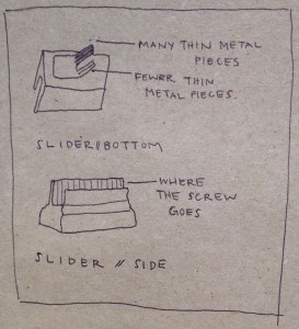
Running a little above the pathway is a screw attached to the side of top cover (not making contact with the base). On the screw there is a slider which makes contact with both high resistance and low resistance pathway on the surface of the base.
You can turn the screw and as the screw turns, the slider precisely slides along the fine threading of the screw. When the slider moves along the screw, it changes it’s position where it makes surface contact with the two pathways it’s riding along. It in turn changes the resistance running through the circuit that’s made between the one path going from leg 1 to 3, through the slider and down the other path that leg 2 is connected to. By changing the position of the slider (using the turning motion of the screw) you can change the amount of resistance that you receive as an output. That’s how you can adjust and create different current levels by using only one circuit !
